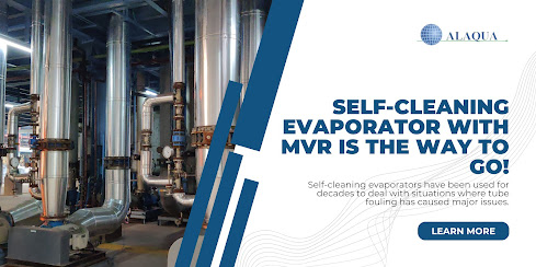
Self-cleaning evaporators have been used for decades to deal with situations where tube fouling has caused major issues. For the past few years, Alaqua, a processing equipment such as evaporators supplier in the USA, for a variety of industries, has been actively working to deliver Multi-Effect Evaporator (MEE) facilities to treat problematic effluent from dye-stuff manufacturers.
Self-cleaning is one of the effects of these plants, as are forced circulation and other effects. The sole rationale for simply equipping one of the effects with the self-cleaning configuration is solely financial. Self-cleaning technology will cost more CAPEX, but it will increase the plant's availability and efficiency while also reducing cleaning expenses.
So, choosing the effect that is most prone to fouling can help extend the period between cleanings significantly, but it also means that the other effects may still display fouling. This is one of the main reasons why a Mechanical Vapor Recompression (MVR) approach is so appealing: there will be only one effect. As a result, the question of which effect to use self-cleaning technology on is no longer relevant.
The vapor from evaporation is squeezed by a compressor to a greater pressure and temperature in an evaporator driven by an MVR (or MVC, which are synonyms). This greater temperature permits the vapor to condense on the evaporator's shell side of the heat exchanger. To put it another way, all of the energy consumed to evaporate or recover latent heat is reclaimed. This is only partially done in an MEE by definition. Of course, energy is required to run the compressor in the MVR, but the overall use of primary energy is greatly reduced.
Evaporators That Self-Clean By Using Fluidized Bed
The passage of solid cleaning particles through the tubes of a vertical shell and tube heat exchanger is how the self-cleaning fluidized bed evaporator works. The fouling liquid rises via the tube bundle of the heat exchanger, which contains specially designed intake and output channels. The solid particles are delivered to the fluid in the input channel using a patented distribution method to achieve a uniform distribution of particles throughout all tubes.
The particles (usually stainless steel or ceramic particles with a size between 1 and 4 mm) are fluidized by an upward flow of liquid, where they provide a moderate scouring effect on the heat exchanger tubes' walls, eliminating any deposit before it forms fouling. The particles detach from the liquid in the separator after the tube bundle is removed and returned to the inlet channel via an external downcomer, and the cycle is repeated.
Particles from the downcomer are pushed into the intake channel with a portion of the incoming flow to the heat exchanger, enabling the number of particles supplied to the inlet to be adjusted.
Many forms of fouling deposits, hard or soft, resulting from biological, crystallization, chemical, or particle fouling mechanisms, or a mix of these, may be efficiently treated with the self-cleaning evaporator.
MVR Design, Liquid Composition Effects, and Fouling:
The composition of the liquid, the compressor performance, and the needed heat transfer area all play a role in the thermal design of an MVR. The temperature increase delivered to the vapor is determined by the compressor design and selection, and the driving force for heat transfer between the condensing vapor and the liquid at the tube side is determined by the driving force for heat transfer between the condensing vapor and the liquid. The needed heat transfer area (HTA) decreases as the temperature difference increases. The compressor, on the other hand, will use more energy as the temperature rises.
The composition of the liquid has an impact on the required temperature rise. The reason for this is that salts, in particular, raise the boiling point. The temperature differential between vapor and shell is reduced by this boiling point elevation (BPE). If the BPE is 8, a liquid will boil at 108°C if the vapor from an atmospheric evaporating system is 100°C. When the two-stage compressor raises the temperature by 16°C, the vapor condenses at 116°C.
The heat transfer driving power is around 8 degrees at this point. There would be no driving power remaining in a single-stage compressor with an 8-degree temperature rise. The required heat transfer will be directly proportionate to the temperature difference once BPE has been taken into account. When the BPE is underestimated, the HTA chosen is likely to be too small, resulting in a ten-percentage-point capacity decrease.
Since fouling may readily lower the coefficient of transfer by 20% to 50% or more, the development of scales can have a significant impact on evaporation capacity. This is one of the reasons why self-cleaning technology is so appealing. It maintains plant capacity and avoids overdesign.
Compressors are used for the operational aspect:
Compressor functioning will necessitate minor facility maintenance. When compared to turbofans, root blowers require less maintenance and require less attention. Turbofan impellers spin swiftly and have a high tip speed, causing vibration difficulties if they become dirty.
Vibrations should be monitored and the fan should be turned off as soon as possible to avoid major damage. MVR compressors have a high level of reliability when it comes to compressor maintenance.
Conclusion:
To summarise, employing a self-cleaning evaporator with an MVR is the best approach to save primary energy while treating effluent and optimizing the self-cleaning heat exchanger's capacity.
Alaqua is USA-based processing equipment such as crystallizer, heat exchanger, solvent recovery, spray dryer, distillation, and evaporator supplier worldwide to various food, pharmaceutical, chemical, environmental, and power generation industries. They also offer various processing equipment services such as installation and commissioning, retrofitting, troubleshooting, etc. services for the abovementioned equipment. Contact them for queries, information, equipment, and services!

